Khmelnytskyi company "Valon-A" offers TSGL dry transformers. +38(0382)74-99-20
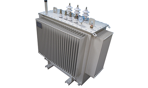
TSGL dry power transformers are manufactured with a capacity of 160 to 2500 kVA for a nominal primary winding voltage of 6 or 10 kV and a nominal secondary winding voltage of 0.4 or 0.23 kV at a frequency of 50 Hz. The scheme and group of winding connections are U/Un-0 or D/Un-11.
Type of climatic performance U3 according to GOST15150.
Normal operation of transformers is ensured under the following conditions:
1. Altitude above sea level - no more than 1000 m;
2. The environment is explosive, not containing conductive dust, aggressive gases and vapors in concentrations that reduce the parameters of the transformer substation within unacceptable limits;
3. Atmosphere type - II according to GOST15150;
4. Ambient temperature - from -25°C to + 40°C.
Voltage regulation is carried out by switching without excitation (PBZ) with the transformer disconnected from the network both from the higher and lower voltage sides. The voltage is regulated from the higher voltage side by ± 2x2.5% of the nominal value using jumpers.
Transformers are equipped with windings with cast epoxy insulation "Geofol" from Tesar, ABB, Siemens, Merlin Gerin, Schneider Elektrik or other companies.
The class of heat resistance of the windings is F, the windings are painted brown.
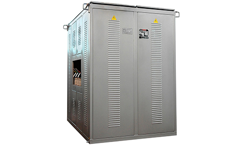
Transformers are manufactured in a casing with a degree of protection IP20, P21 or P22.
Transformers are manufactured in the following types:
1. With the possibility of connecting high and low voltage power cables through the bottom of the casing;
2. With the possibility of connecting high voltage power cables through the bottom of the casing and low voltage busbar terminals on the narrow or wide sides of the transformer (right or left);
3. With the possibility of connecting low voltage power cables through the bottom of the casing and high voltage busbar terminals on the narrow or wide sides of the transformer (right or left);
4. With high and low voltage busbar terminals on the narrow or wide sides of the transformer (right or left);
5. With high and low voltage busbar terminals through the roof of the transformer.